PWM to voltage controlled fan hub conversion
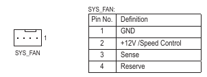
My aging home Xen server has a rather old mainboard. A Gigabyte Z68M-D2H. It has 2 fan headers, but only the CPU FAN supports PWM. The manual shows the SYS_FAN header Pin 4 as “Reserved” - which means no PWM signal. Instead, Pin 2 is marked as “+12V / Speed Control”. The system does this by either using PWM on the +12v line, or decreasing the voltage on it - and you can choose this in the BIOS.
So, normally, we’d use a PWM fan hub to share the PWM signal to the other fans, and draw the power from a molex or SATA connector - so we don’t overload the mainboard header capacity. In this case however, we can’t do that - as we don’t get a signal on Pin 4. What to do? While mulling this over, I looked at how I could hook up my existing PWM hub - but generate a PWM signal elsewhere - and use the voltage output from the mainboard to control the PWM duty cycle - and hence the speed of as many fans that could fit on the hub. Enter an ATTiny85 Arduino!
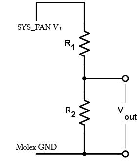
Firstly, I had to make the voltage suitable to go an an analogue pin of the ATTiny85 - which can handle a maximum of 5v. I decided to use a simple voltage divider to split the voltage in a 2/3 and 1/3 split. This should give a maximum of 4v on the analogue pin - giving some headroom for… interesting voltages to be handled. A voltage divider is pretty simple - and made up of two resistors. I used a single 24K ohm resistor for R1, and a single 12K ohm resistor for R2. I used 1% tolerance resistors - just because I had them - but 5% are probably just as good. I tested by measuring the voltage at the junction of the two resistors while having the fan set for full speed - and measured 4.02v.
Now to the code for the Arduino - as this was probably the most complex part. The specification for PWM fans for PC shows that you need a 25Khz signal. I’ve included the full code at the end of this post. It is a modification of this code on Github. I needed to modify the cable included with the PWM hub to pass through pin 2 & 3 from the mainboard to the hub. This gives me the +12v / Speed Control wire - and the sense wire to feed back a speed to the mainboard. The best part of all, the ATTiny85 fits inside the centre of the PWM hub as showed below.
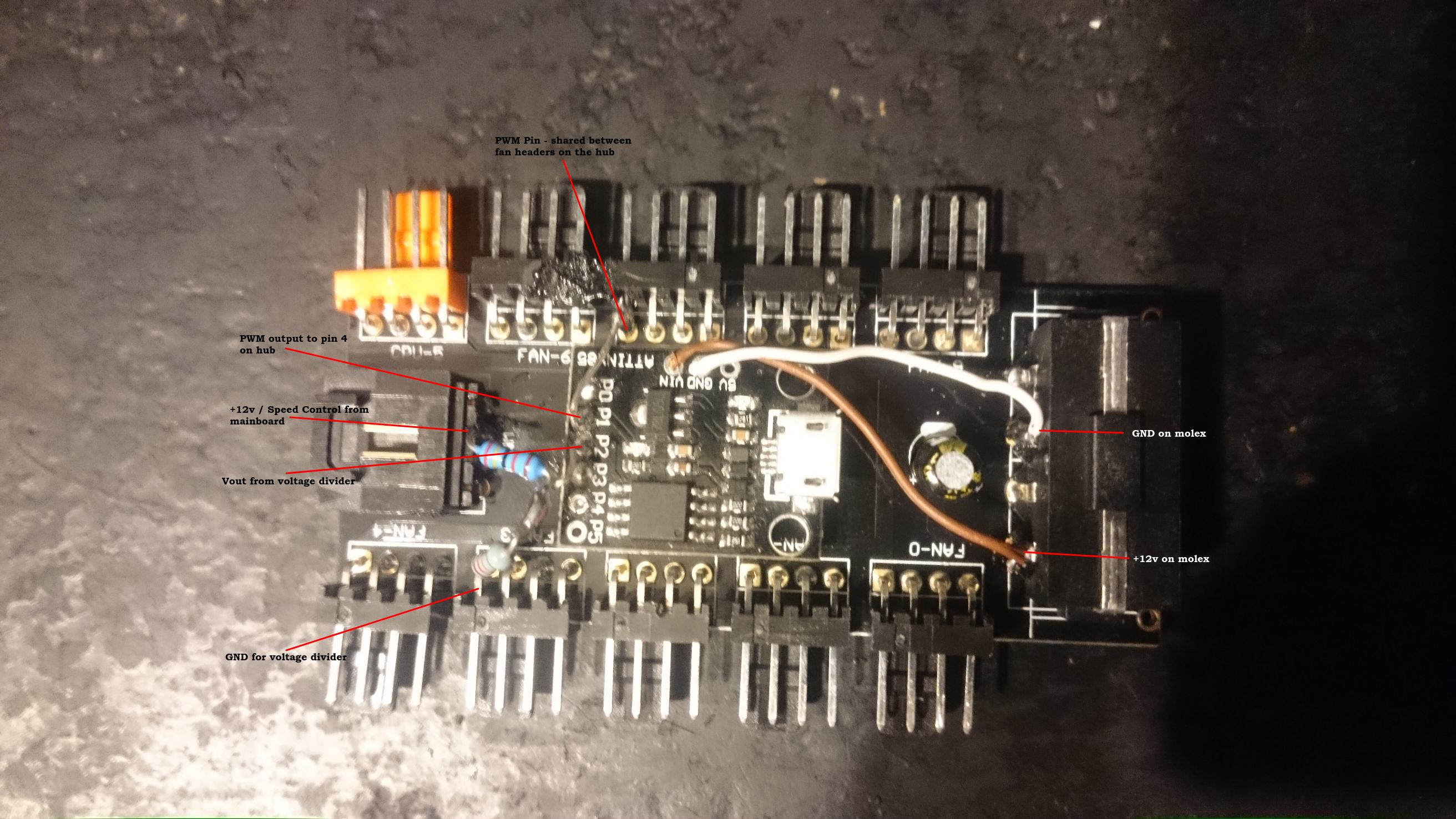
The fan speeds reported back to the mainboard will reflect whatever the fan plugged into the orange fan header reports via the Sense pin.
1
2
3
4
5
6
7
8
9
10
11
12
13
14
15
16
17
18
19
20
21
22
23
24
25
26
27
28
29
30
31
32
33
34
35
36
37
38
39
40
41
42
43
44
45
46
47
48
49
50
51
52
53
54
55
56
57
58
59
60
/*
 *                         ATtiny85
 *                      -------u-------
 *  RST - A0 - (D 5) --| 1 PB5   VCC 8 |-- +5V
 *                     |               |
 *        A3 - (D 3) --| 2 PB3   PB2 7 |-- (D 2) - A1  --> Vout from voltage divider
 *                     |               |
 *        A2 - (D 4) --| 3 PB4   PB1 6 |-- (D 1) - PWM --> Fan Blue wire
 *                     |               |
 *              Gnd ---| 4 GND   PB0 5 |-- (D 0) - PWM --> Disabled
 *                     -----------------
 */

// normal delay() won't work anymore because we are changing Timer1 behavior
// Adds delay_ms and delay_us functions
#include <util/delay.h>		// Adds delay_ms and delay_us functions

// Clock at 8mHz
#define F_CPU 8000000		// This is used by delay.h library

const int PWMPin = 1;		// Only works with Pin 1(PB1)
const int SYS_FAN = A1;		// Use PIN7 / PB2 as a voltage input.

void setup()
{
	pinMode(PWMPin, OUTPUT);
	// Phase Correct PWM Mode, no Prescaler
	// PWM on Pin 1(PB1), Pin 0(PB0) disabled
	// 8Mhz / 160 / 2 = 25Khz
	TCCR0A = _BV(COM0B1) | _BV(WGM00);
	TCCR0B = _BV(WGM02) | _BV(CS00);
	// Set TOP and initialize duty cycle to zero(0)
	OCR0A = 160;	// TOP - DO NOT CHANGE, SETS PWM PULSE RATE
	OCR0B = 0;	// duty cycle for Pin 1(PB1)
}

void loop()
{
	int in, out;

	// Read the voltage from the SYS_FAN header
	in = analogRead(SYS_FAN);

	// 4v input should be (1024 / 5) * 4 - or close enough to 820. Use this as 100% duty cycle
	// However, if we read *over* 4v, clamp it to 820 anyway.
	if ( in > 820 ) {
		 in = 820;
	}

	// If we lose the SYS_FAN voltage, we don't want to STOP the fans.
	// Use a lowish value to just keep things spinning slowly as a failsafe.
	// On my setup - this is ~1100rpm
	if ( in < 200 ) {
		in = 200;
	}

	out = map(in, 0, 820, 0, 160);
	OCR0B = out;
	_delay_ms(200);
}